Architectural Anti-Glare Optical Design: Visual Comfort and UGR Compliance Guide
Visual comfort has evolved from an aesthetic preference to a core technical requirement in modern commercial lighting design. Workplace ergonomics and architectural specifications place increasingly stringent demands on optical shielding, brightness control, and luminance distribution. In high-density office layouts, educational facilities, healthcare environments, and commercial interiors, unshielded LED light sources often introduce intense direct and reflected glare, causing visual fatigue, eye strain, headaches, and decreased productivity among occupants.
To address these critical visual challenges, optical engineers, fixture designers, and architectural specifiers rely on standardized evaluation metrics such as the Unified Glare Rating (UGR), established by the International Commission on Illumination (CIE). Achieving a low UGR rating without compromising overall luminaire optical efficacy (measured in lumens per watt) requires specialized optical architectures and micro-structured light control media. This comprehensive engineering guide explores the fundamental physics of glare, mathematical UGR calculation formulas, advanced optical shielding control technologies, and practical project specification criteria for high-performance visual environments.
1. Understanding Glare Physics: Direct vs. Discomfort Glare
Lighting-induced glare is broadly classified into two distinct visual phenomena: disability glare and discomfort glare. Disability glare physically reduces visual capability through light scattering within the optical media of the human eye, directly obscuring visual detail. Discomfort glare, by contrast, produces visual annoyance, discomfort, or psychological fatigue without necessarily impairing immediate object recognition or visual acuity.
In interior commercial spaces, discomfort glare represents the primary engineering challenge for luminaire manufacturers and lighting design professionals.
Key Factors Governing Glare Perception
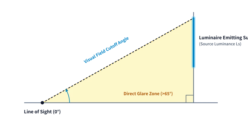
The sensation and intensity of glare experienced by an observer depend on four physical and spatial parameters described in optical engineering:
- Source Luminance (\(L_s\)): The luminous intensity emitted per unit apparent area of the light-emitting surface (\(cd/m^2\)). High-density surface-mount LED arrays present extreme source luminance when viewed directly without diffuser shielding.
- Background Luminance (\(L_b\)): The surrounding ambient field brightness against which the light source is observed. High contrast between a bright luminaire optical aperture and a dark ceiling grid significantly exacerbates perceived discomfort glare.
- Solid Angle (\(\omega\)): The angular size of the luminaire emitting surface viewed from the observer eye location. Larger emitting surfaces positioned at close proximity contribute proportionally more to total visual glare intake.
- Position Index (\(p\)): The spatial displacement of the light source relative to the observer direct horizontal line of sight (Guth Position Index). Light sources located directly within the primary visual field produce significantly higher discomfort than those situated at steep high-angle cutoff positions above the line of sight.
Managing direct glare requires precisely shaping luminaire light output above specific viewing angles—typically limiting surface luminance at angles exceeding 65 degrees from the vertical downward axis (\(0^\circ\) nadir).
2. Mathematical Foundation of the Unified Glare Rating (UGR)
The International Commission on Illumination defined the Unified Glare Rating system in Publication CIE 117 to quantify discomfort glare from interior electric lighting installations.
The Standard UGR Equation
The fundamental formula for calculating the UGR value from a luminaire array is expressed mathematically as:
$$UGR = 8 \log_{10} \left( \frac{0.25}{L_b} \sum \frac{L_s^2 \cdot \omega}{p^2} \right)$$Where:
- \(L_b\) is the background luminance (\(cd/m^2\)).
- \(L_s\) is the luminance of the luminous parts of each luminaire in the direction of the observer eye (\(cd/m^2\)).
- \(\omega\) is the solid angle of the luminous parts of each luminaire at the observer eye (\(sr\)).
- \(p\) is the Guth position index for each individual luminaire, accounting for location relative to the line of sight.
Standard UGR Thresholds in Architectural Standards
Building energy codes, interior lighting standards (such as EN 12464-1), and WELL Building Standard guidelines across global commercial markets establish maximum allowable UGR limits based on visual task complexity:
| Application Space | Target UGR Rating | Visual Sensitivity & Ergonomic Requirement |
|---|---|---|
| Technical Drafting & Precision Engineering | \(\le 16\) | Critical visual accuracy, prolonged high-contrast technical reading |
| Standard Open-Plan Offices & Classrooms | \(\le 19\) | Computer workstation tasks, general visual comfort standards |
| Reception Desks & Conference Rooms | \(\le 22\) | Interpersonal communication, transient visual tasks |
| Corridors, Restrooms & Circulation Paths | \(\le 25\) | General spatial orientation, low visual difficulty |
| Warehouses & Industrial Storage Facilities | \(\le 28\) | Coarse material handling, safety navigation |
Specifiers must recognize that UGR is a system calculation evaluated for a specific room geometry, surface reflectance values, observer location, and luminaire array layout—not an isolated intrinsic property of a single luminaire fixture. However, manufacturers publish standardized UGR reference tables based on tabular room dimensions (\(4H/8H\), reflectances 70/50/20) to enable direct comparison between luminaire optical performance.
3. Optical Shielding and Control Technologies
To achieve UGR \(\le 19\) or UGR \(\le 16\) while maintaining system energy efficiency, commercial luminaires employ specialized optical elements engineered to bend, diffuse, or absorb high-angle light rays.
Micro-Prismatic Diffusers (MPD)
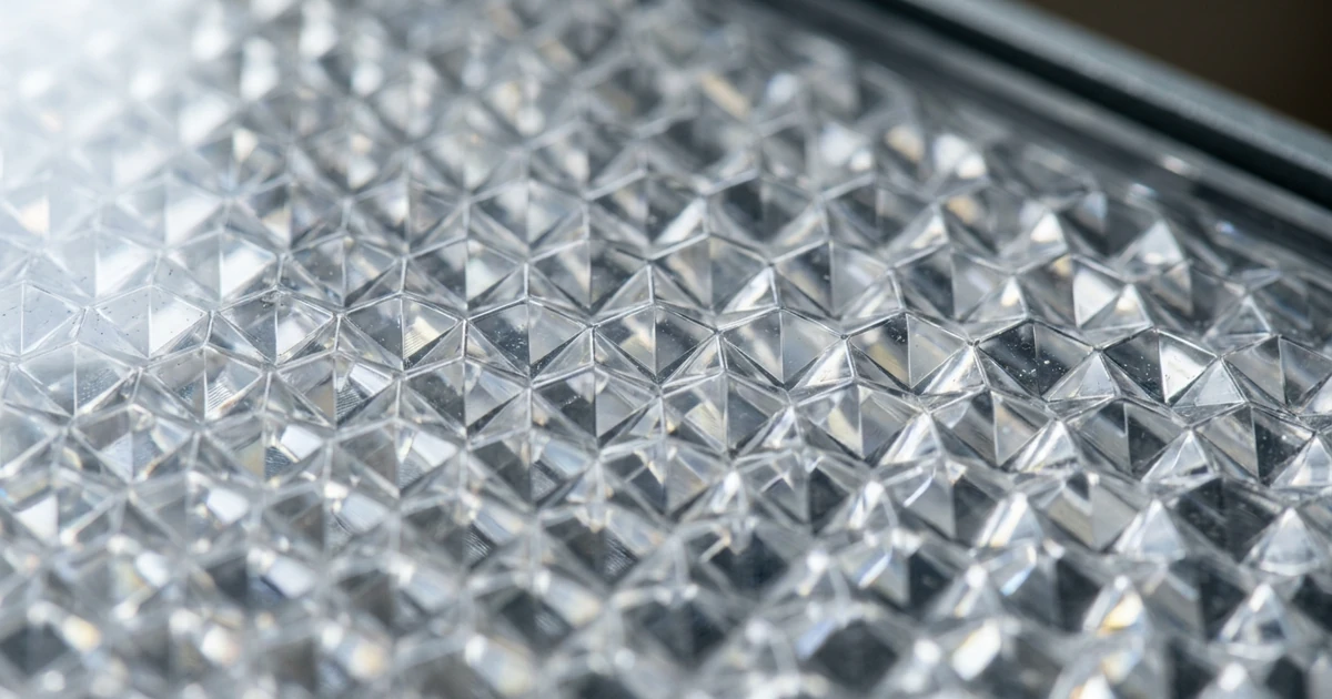
Micro-prismatic optical sheets feature microscopic geometric prisms molded or laser-etched into acrylic (PMMA) or polycarbonate matrix sheets. Unlike standard opal diffusers that scatter light uniformly in all directions (Lambertian distribution), micro-prismatic optics refract light entering at high angles inward toward the nadir (\(0^\circ-45^\circ\) cone).
- Mechanism: Refraction through calculated prism apex angles (typically \(60^\circ\) to \(90^\circ\)).
- Optical Transmittance: High system efficiency (\(82\% - 88\%\)).
- Luminance Control: Effectively suppresses light output above the \(65^\circ\) cutoff angle, preventing visual glare at standard desk viewing angles while maintaining high downward illuminance.
Deep-Recessed Reflectors and Regressed Optics
Regressed architectural optics position the LED light source deep inside the luminaire housing behind a physical mechanical baffle or architectural reflector cone.
- Cutoff Angle: Physical mechanical shielding restricts direct line of sight to the LED light source unless the observer stands directly under the fixture.
- Secondary Reflectors: Matte metallic, specular anodized, or white micro-textured internal reflectors control beam distribution while minimizing secondary surface reflection brightness.
Honeycomb Louvers and Baffle Grids
Honeycomb louvers consist of hexagonal micro-cell arrays placed directly across the luminaire optical aperture.
- Directional Control: Physically absorbs wide-angle stray light rays falling outside the target beam angle.
- Aesthetics: Delivers a dark-light effect where the ceiling aperture appears dark and unlit even when the luminaire is fully energized.
- Trade-off: Lower overall fixture optical efficiency (\(65\% - 75\%\) light exit ratio) due to internal light absorption along grid cell walls.
4. Comparing Anti-Glare Optical Architectures
When evaluating optical control systems for architectural projects, specifiers must balance glare suppression capability, total optical efficiency, beam distribution uniformity, and aesthetic ceiling integration.
| Optical Architecture | Achievable UGR Range | Optical Efficiency (\(\eta\)) | Beam Characteristics | Primary Commercial Applications |
|---|---|---|---|---|
| Standard Opal Diffuser | \(UGR > 22\) | \(70\% - 78\%\) | Wide Lambertian, uniform surface glow | Circulation paths, utility spaces |
| Micro-Prismatic + Diffuser Film | \(UGR \le 19\) | \(80\% - 86\%\) | Controlled batwing / batwing asymmetric | Office troffers, linear pendants |
| Deep-Recessed Regressed Reflector | \(UGR \le 16\) | \(82\% - 90\%\) | Precise spot / flood optical cone | High-end executive suites, hospitality |
| Honeycomb Louver Grid | \(UGR \le 16\) | \(65\% - 75\%\) | Tight directional cutoff, low spill | Accent downlights, task lighting |
| Multi-Lens Mini-Downlight Array | \(UGR \le 16\) | \(85\% - 92\%\) | Individual TIR lens distribution | Architectural linear office systems |
Selecting the optimal optical strategy depends on target lux levels, ceiling mounting heights, and specific work plane requirements.
5. Case Studies and Selection Recommendations for Commercial Projects
Real-world commercial office projects require tailored optical selection based on spatial layout, ceiling heights, and task types.
Case Study: Corporate Headquarters Open-Plan Office Retrofit
In a corporate office retrofit project involving 4,000 square meters of open-plan workstation space, replacing standard opal panel fixtures with micro-prismatic linear pendant luminaires reduced average workplace UGR from 22.4 to 17.1. This optical upgrade maintained 500 lux on desktop task planes while achieving a 14% net energy saving through improved optical downward utilization.
Selection Recommendations Matrix
- For Open Workstations with High Monitor Density: Select Micro-Prismatic Diffusers combined with secondary optic films to guarantee UGR \(\le 19\) across all viewing angles.
- For Conference Rooms & Executive Spaces: Recommend Deep-Recessed Mini-Downlight Arrays or Honeycomb Louvers for maximum glare control (UGR \(\le 16\)) and premium architectural integration.
- For Educational Classrooms & Training Rooms: Deploy batwing micro-prismatic optical distributions to ensure uniform illuminance across whiteboards and student desks without direct glare.
6. Visual Comfort and Ergonomics in Modern Workspaces
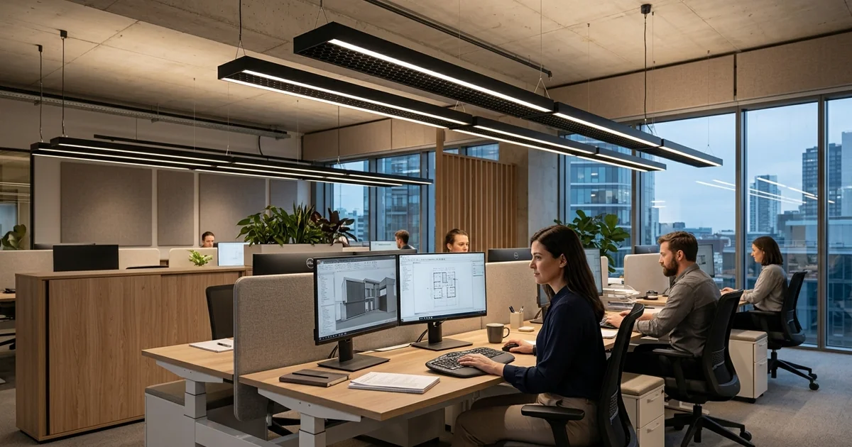
Modern commercial visual ergonomics extends beyond basic horizontal task illuminance requirements. The widespread adoption of display screens demands strict control of reflected glare on vertical glass surfaces.
Vertical Illumination and Luminance Uniformity
Achieving complete visual comfort requires balancing horizontal task illuminance (\(E_h\)) with vertical illuminance (\(E_v\)) on walls and vertical work planes. High ratios of horizontal-to-vertical illuminance create cave-like visual environments with dark perimeter walls, increasing visual contrast strain and occupant discomfort.
- Luminance Ratios: The luminance ratio between task area, immediate surround, and background surfaces should not exceed \(3:1\) and \(10:1\) respectively.
- CIE Cutoff Criteria: Luminaires installed above computer workstations must maintain average surface luminance \(< 1,500\ cd/m^2\) or \(< 3,000\ cd/m^2\) at angles of \(65^\circ, 75^\circ,\) and \(85^\circ\) relative to vertical downward axis, depending on monitor screen gloss characteristics (EN 12464-1 clause 5.3.2).
7. Frequently Asked Questions (FAQ)
Q1: What is the main practical difference between UGR \(\le 19\) and UGR \(\le 16\)?
A UGR \(\le 19\) is the standard benchmark requirement for general office and classroom environments, ensuring comfortable viewing for computer task work over extended shifts. A UGR \(\le 16\) offers superior visual comfort, specified for high-precision technical drafting, healthcare operating spaces, executive boardrooms, and luxury architectural environments.
Q2: Can a single standalone luminaire fixture have a fixed UGR rating?
No. UGR is a system-level calculation based on overall room dimensions, surface reflectance values, luminaire layout density, and observer viewing position. However, luminaire manufacturers perform testing in standardized reference room geometries (\(4H/8H\)) to provide comparative UGR tables across different optical models.
Q3: How do micro-prismatic diffusers maintain efficiency compared to louver grids?
Micro-prismatic diffusers control high-angle light primarily through optical refraction rather than physical absorption. This allows light entering at high angles to be redirected downward into the useful task zone with minimal optical energy loss, achieving system optical transmittance of \(82\% - 88\%\) compared to \(65\% - 75\%\) for internal absorber louvers.
8. Specification and Verification Checklist for Lighting Designers
To verify compliance and ensure intended visual comfort outcomes during project delivery, procurement teams and lighting specifiers should execute a systematic review process:
Step 1: Photometric File Inspection (.IES / .LDT)
Request certified polar intensity distributions measured in accredited photometric testing laboratories. Confirm that high-angle luminous intensity (\(cd/1000\ lm\)) declines sharply above the \(65^\circ\) cutoff angle.
Step 2: Tabular UGR Verification
Examine standard UGR tables embedded in photometric files for standard reference room proportions (\(4H/8H\), reflectances \(C:70\%, W:50\%, F:20\%\)). Ensure values for both crosswise and endwise observer positions fall within specification limits.
Step 3: Simulation Software Modeling
Incorporate exact luminaire photometric files into software calculation environments (such as Dialux EVO or Relux). Calculate specific observer grids at desktop viewing height (\(1.2\ m\) seated position) across all working zones.
Step 4: Sample Physical Mock-up Evaluation
Perform visual inspection of physical samples in a real-world test room. Evaluate direct line-of-sight visual comfort, thermal dissipation stability, and mechanical fit within specified ceiling grid systems.
Conclusion and Next Steps
Architectural anti-glare design is an essential engineering discipline combining optical physics, human ergonomics, and precision optical manufacturing. By deploying micro-prismatic diffusers, deep-recessed optics, and controlled lens arrays, specifiers can achieve UGR \(\le 19\) or UGR \(\le 16\) performance without sacrificing system energy efficacy. High-quality optical designs enhance workplace comfort, support visual health, and meet global commercial energy and building standards. For technical specification support or customized photometric simulation files, contact our engineering team.